Mechanical engineering design basics
For static loading on a structure, fundamental analysis is as follows:
- Stress;bending or axial depending on type of loading
- Static deflection
- Failure criteria; mode of analysis which failure is to be judged. This can include thermal, shear, bending, fatigue, yield etc
- Thermal expansion
From mechanical engineering textbooks, stress in, axially loaded structure is:
where: = stress in the direction of loading, P = internal load, A = cross sectional area
Stress in bending is :
where: = bending stress, M = bending moment; moment cause by applied load, y = distance where stress is calculated measured from shape centroid, I = second moment of area
Strain in the elastic range can be determined using Hooke’s law, which is defined as follows:
where: E = material elastic modulus, = strain
Per “Mechanics of Materials 9th edition”, elastic deflection for structures varies depending on support and type of loading. Consult textbook. As an example, simply supported beam in bending,deflection is:
where: = deflection, P = applied force, = location where deflection to be computed, L = total length of the beam, E = material elastic modulus; I = second moment of area
Linear thermal expansion is defined as:
where: L = linear length, = change in temperature, = material coefficient of expansion
All other properties, such as fatigue, fracture, von Mises stress will be discussed at a later date
To show the application of these equations, analyse a cantilevered beam with configuration as follow:
- Square cross section - 25mm x 25mm
- Length 250mm
- Material assumed to be Aluminium 6061-T6
- Fixed support at one end
- 100kg applied ( for axial applied in axial direction; for bending applied in Z direction)
- Temperature difference = 100K (for thermal analysis only)
Graphical represenation of the beam is shown in the figure. Geometry is simple, however mentioned formulas apply to both simple & complicated geometries.

With the information defined, applying the equations mentioned before stress and deflections can be determined. Beam axially loaded with 100kg results :
Results can be compared against the FEA results shown below
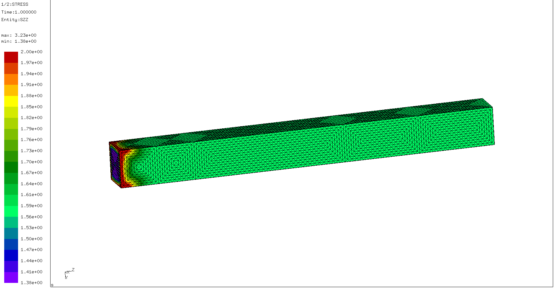
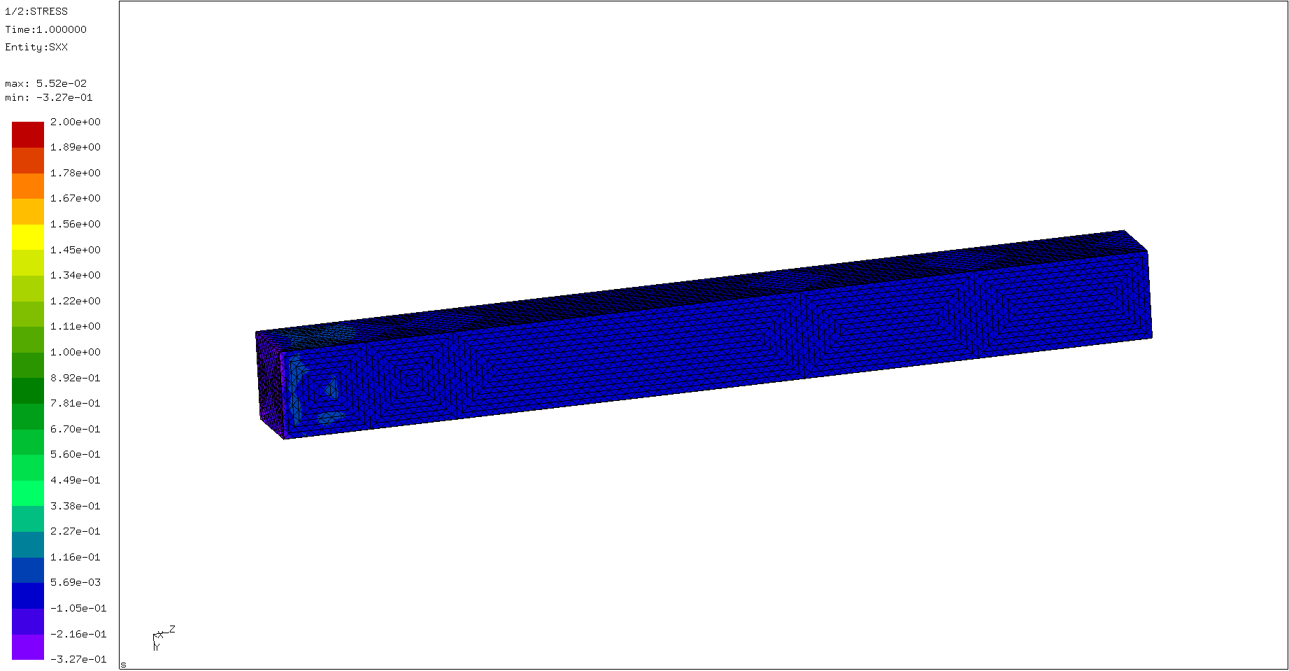
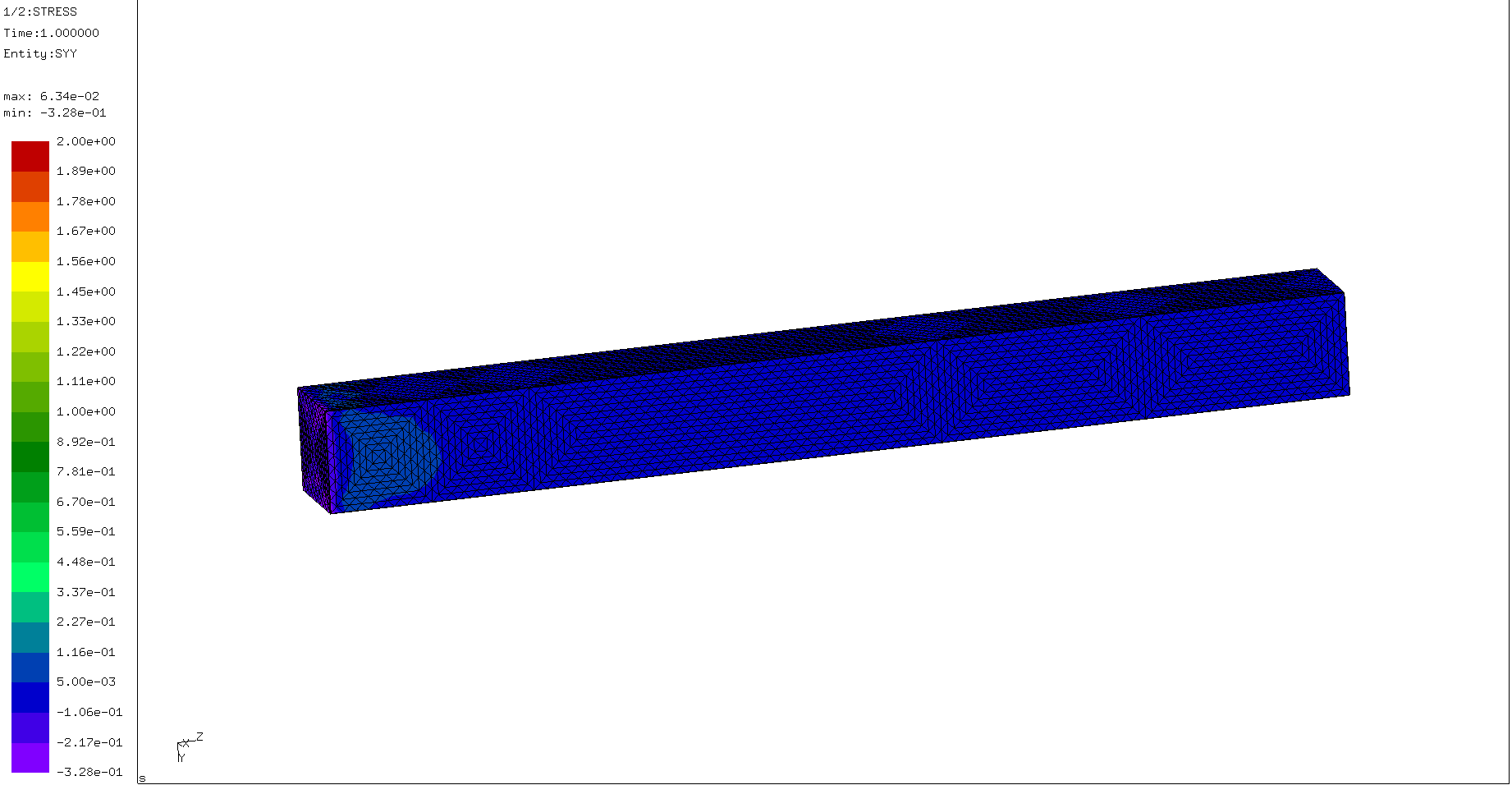
Two conclusions can be drawn from the FEA results:
- Stress in the Z-direction is as was calculated from the formula. As is seen in the figure, maximum stress (red area) is 2MPa; most of the beam is the green colour, which happens to be exactly 1.57 as calculated previously.
- From the other two figures, stress is all very low (blue colour); this is as expected as load is only axial.
Applying Hooke’s law, strain is found as:
Once again, checking the result against simple FEA model. Displacement results can be seen figure below.
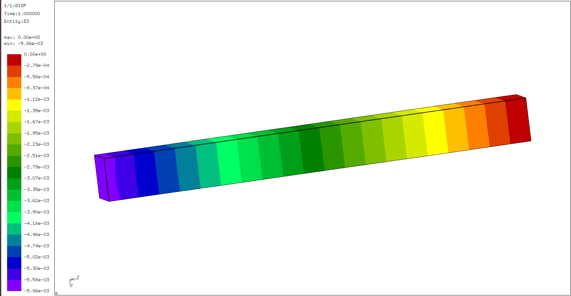
Figure displays displacement, however Hooke’s law determines strain. Therefore it is required to convert displacement to strain. The conversion is done using the procedure:
where: D is displacement, L is length
Therefore from displacement figure, maximum displacement is . At maximum displacement, length is 250mm. Using conversion formula, strain is:
Bending stress is a little more involved, however following the equation above (100kg loading still being applied); bending stress in beam is:
Maximum deflection occurs where = L i.e. . Therefore, with the applied 100kg, deflection in the beam is:
Both stress and displacement were calculated. Results seen in the figures below.
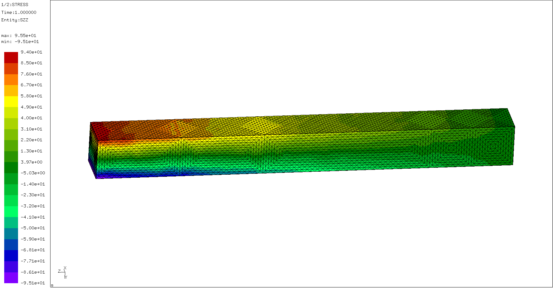
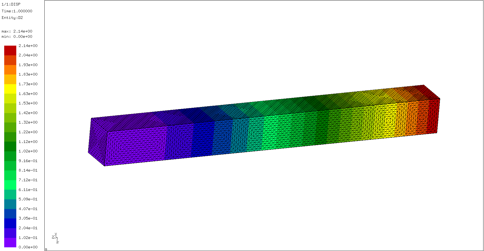
Stress is found to be 95MPa and deflection is found as 2.14mm. Stress distribution is positive on the top surface and negative on the bottom surface. This shows that top surface is in tension and bottom surface is in compression; expected behaviour of a beam in bending. Both results are very close to the hand calculations. Therefore, it can confidently be said that FE simulation and hand calculations are both correct.
In conclusion, making use of simple basic mechanics theories can enable us to accurately identify behaviour of the structure. Having determined stress levels and displacements, this is the basis of failure theory. Based on such information, we can accurately predict failure of a structure.
